Duct Design in Cement Plants: How It Impacts Pressure Drop, Airflow & Fan Power

Duct design

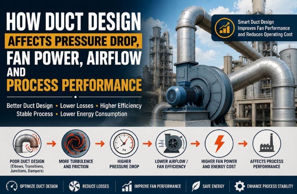
In a cement plant, high fan power or low airflow is often blamed on the fan itself. However, the fan is only one part of the overall air-handling system. The complete system includes the ductwork, elbows, transitions, junctions, dampers, filters, cyclones, and the fan inlet and outlet arrangement. All of these components contribute to the resistance the fan has to overcome.

If the duct system is poorly designed, it can create unnecessary turbulence, flow separation, friction losses, and fan system effects. As a result, the pressure drop can increase, airflow may fall below the required level, and the fan may need to run at a higher speed or consume more power to maintain the required flow. This is why duct design should be considered an important part of fan and process optimisation in a cement plant. Duct fittings such as elbows, transitions, junctions, and dampers contribute to pressure losses, while poor airflow conditions at the fan inlet or outlet can create additional system effects and affect fan performance.

Why Is Duct Design Important in Cement Plants?

A cement plant handles a large volume of process gases every day, and these gases have to move through different equipment and ducting systems. Ducts are an essential part of several process areas, including:

  • Kiln and pre-heater gas circuits
  • Raw mill, Coal mill, Cement mill and Cooler vent systems
  • Bag filter and ESP circuits
  • Material and dust extraction systems

As the gas moves through the system, it encounters resistance from the ductwork, fittings and process equipment. The fan has to provide enough pressure to overcome this total resistance and maintain the required airflow. In a simplified form:

ΔP₍system₎ = ΔP₍duct₎ + ΔP₍fittings₎ + ΔP₍equipment₎

This is why unnecessary resistance in the duct system can have a direct effect on fan operation. If the ductwork creates more pressure loss than necessary, the fan may need to operate at a higher pressure or speed to maintain the required airflow. Fan power is also related to airflow and pressure rise. A simplified relationship is:

Power = Q × ΔP / η

where:

  • Q = airflow
  • ΔP = pressure rise
  • η = overall fan and drive efficiency

So, when avoidable pressure losses are present in the system, the fan has to do more work to move the same amount of gas. Over time, this can translate into higher electrical consumption and increased operating costs. For this reason, duct design is not just a piping or layout consideration. It is directly connected with fan performance, airflow control, energy consumption, and overall process stability.

10 Common Duct Design Problems and Their Impact

1. Sharp 90° Elbow

A sharp 90° elbow makes the gas change direction abruptly. This sudden change disturbs the flow and can lead to flow separation, secondary flow and increased turbulence inside the duct. As a result, the elbow can create additional pressure loss and may also produce a non-uniform velocity profile downstream.

A properly designed long-radius elbow generally provides smoother airflow and lower aerodynamic losses than a sharp bend. However, the actual pressure loss depends on factors such as the elbow geometry, radius, gas velocity, and flow conditions. The location of the elbow is also important. If a sharp bend is installed too close to the fan inlet, the disturbed or swirling airflow entering the fan can affect its performance. This is commonly referred to as a fan system effect.

Better approach:
Wherever the plant layout allows, use a suitably designed long-radius elbow or another low-loss fitting, particularly near fan inlets and other locations where smooth airflow is important wherever plant layout permits.

Sharp 90° Elbow -  Common Duct Design Problems and Their Impact

2. Sudden Expansion

When gas moves from a smaller duct into a larger duct, its velocity decreases. If the expansion is too sudden, it can cause flow separation, turbulence, and recirculation, leading to additional total-pressure loss. A gradual transition allows the gas to expand more smoothly and generally reduces these losses. During an expansion, some velocity pressure can be recovered as static pressure, but turbulence and mixing still cause a loss of total pressure.

So, a sudden expansion does not simply mean that static pressure always increases or that all pressure is lost. The actual effect depends on the duct geometry and flow conditions.

Better approach:
Use a gradual transition wherever practical, especially in high-flow process gas ducts where pressure loss is important.

Sudden Expansion

3. Sudden Contraction

When gas moves from a larger duct into a smaller one, the flow area decreases and the gas velocity increases.

Q = A × V

where Q is airflow, A is duct area, and V is gas velocity.

If the contraction is too sudden, it can create turbulence and additional pressure loss. A gradual transition generally gives the gas a smoother flow path and helps reduce these losses. However, in cement plants, duct sizing is not only about reducing pressure drop. When the gas contains dust, the velocity must also be high enough to keep particles moving. If the velocity is too low, dust can settle inside the duct and gradually increase resistance. So, good duct design needs to balance low pressure loss with sufficient dust-transport velocity.

Sudden Contraction

Key principle:

Low pressure loss + adequate dust-transport velocity = better duct performance

4. Multiple Bends

Every bend in a duct adds some resistance to the airflow. A few bends are often necessary because of plant layout, but unnecessary elbows, offsets, and repeated direction changes can increase the overall pressure loss. The pressure loss of a fitting can be estimated as:

ΔP = K × ½ρV²

where K is the fitting loss coefficient, ρ is gas density, and V is gas velocity.

Not all bends create the same loss. The actual resistance depends on the bend geometry, radius, gas velocity, and how nearby fittings are arranged. In long cement plant duct circuits, these small losses can add up. Keeping the duct route as simple and smooth as practical can help reduce unnecessary resistance and make it easier for the fan to maintain the required airflow.

image 41

5. T-Junctions and Branch Connections

A 90° T-junction can disturb the airflow when two gas streams meet, creating turbulence and uneven flow distribution. This can increase pressure loss and cause unequal airflow between branches. A properly designed Y-junction or angled branch can provide a smoother flow path, but it is not always better than a T-junction. The right choice depends on the airflow, duct size, branch angle, pressure conditions, dust loading, and flow direction.

In cement plants, these small losses can become significant when several branches and fittings are used in the same gas circuit. Therefore, branch connections should be selected based on actual flow requirements and pressure-loss characteristics rather than just their physical appearance.

T-Junctions and Branch Connections

6. Partially Closed Damper

A partially closed damper restricts airflow and adds resistance to the duct system. As the damper closes further, the pressure drop across it increases, which can affect the fan operating point and reduce airflow. However, dampers are not always a problem. They are commonly used for airflow control, balancing, isolation, and equipment protection. If the process requires frequent airflow adjustment, a VFD may be a more energy-efficient option because it controls the fan speed instead of creating extra resistance by throttling the airflow.

The main objective is to avoid unnecessary damper restriction and operate the system as efficiently as practical efficient method of controlling fan speed, but the appropriate control strategy depends on the process and fan system.

7. Undersized Duct

An undersized duct has a smaller flow area, so for the same airflow, the gas velocity increases.

Q = A × V

Higher velocity generally means higher friction and fitting losses. For example, increasing velocity from 15 m/s to 20 m/s increases velocity pressure by about 78%. However, making the duct unnecessarily large is not the solution either. In dust-laden gas systems, very low velocity can allow particles to settle inside the duct. The goal is to select a duct size that provides reasonable pressure loss while maintaining sufficient velocity for reliable dust transport.

8. Rough or Dirty Internal Surface

The condition of the duct’s internal surface can also affect pressure loss. Dust build-up, corrosion, damaged liners, weld projections, or other obstructions can increase resistance. Dust accumulation is particularly important because it reduces the effective flow area. As the area decreases, gas velocity can increase and pressure loss may rise further.

Regular inspection and cleaning of dust-handling ducts can help prevent excessive build-up and maintain stable airflow.

9. Flexible or Corrugated Duct

Flexible and corrugated ducts generally offer more resistance than smooth, properly installed rigid ducting. The resistance can become higher if the flexible duct is compressed, sagging, sharply bent, or poorly supported. For cement plant applications, duct construction also needs to suit the actual operating conditions, including temperature, abrasion, dust loading, and corrosion.

Wherever possible, flexible duct should be installed properly and kept as straight and fully extended as practical.

10. Abrupt Direction Changes

S-bends, offsets, and zigzag duct routes may sometimes be necessary because of plant layout. However, unnecessary changes in direction can create additional turbulence and fitting losses. A simpler and smoother duct route generally provides better airflow and lower resistance. The objective is not to remove every bend, but to avoid unnecessary changes in direction and aerodynamic resistance.

Fan Inlet and Outlet: A Critical Area

Duct design becomes particularly important around the fan because the airflow condition at the fan inlet and outlet can directly affect its performance. A fan may perform well under test conditions, but its actual performance can change after installation if the airflow entering the fan is disturbed. Common causes include an elbow placed too close to the fan inlet, swirling airflow, sudden transitions, obstructions, or a poorly designed inlet arrangement.

These conditions can create what is known as a fan system effect. The disturbed airflow may reduce fan efficiency, affect the pressure and airflow delivered by the fan, and in some cases require higher fan speed to achieve the desired performance. The outlet side also needs attention. If an elbow or abrupt transition is installed immediately after the fan, the airflow may not have enough space to develop properly. This can create additional turbulence and system resistance.

Therefore, the duct layout around a fan should be designed carefully. Fan selection and duct design should be considered together, because even a correctly selected fan may not deliver its expected performance if the surrounding ductwork creates poor airflow conditions.

Impact of Poor Duct Design on Cement Plant Performance

Poor duct design does not affect only the duct itself. It can influence fan performance, airflow, draft control, energy consumption, and even the stability of the overall process. Some common effects include:

ParameterPossible Impact
System ΔPIncreases
Fan RPMMay increase
Fan power (kW)May increase
AirflowMay decrease or become unstable
DraftMore difficult to control
Bag filter performanceCan be affected
ESP performanceCan be affected by uneven gas distribution
Dust depositionMay increase
Fan vibrationCan increase with disturbed airflow
MaintenanceMay increase
Electrical consumptionMay increase

However, high fan ΔP does not automatically mean that the duct design is the problem. Other factors should also be checked, such as fan condition, impeller fouling, filter or ESP pressure drop, gas temperature, gas density, damper position, false air, and current process conditions. A proper diagnosis should therefore look at the complete system rather than blaming the duct or fan based on a single parameter.

How to Optimise an Existing Duct System

Before making any changes to an existing duct, first identify where the actual pressure loss is coming from. Changing the duct without proper measurements can solve the wrong problem. A basic system check should include:

1. Airflow

  • Actual airflow
  • Design airflow
  • Gas temperature
  • Gas density

2. Pressure

  • Fan inlet and outlet pressure
  • Duct pressure drop
  • Bag filter or ESP ΔP
  • Cyclone ΔP

3. Fan

  • Fan RPM
  • Motor power and current
  • Impeller condition
  • Airflow condition at the fan inlet

4. Duct

  • Number and type of bends
  • Elbow geometry
  • Transitions and junctions
  • Damper position
  • Dust accumulation
  • Possible air leakage

Once the measurements are available, compare the actual operating conditions with the design values. After any modification, check the same parameters again to confirm whether the change has actually improved the system. This approach helps avoid a common mistake in plant troubleshooting: changing the duct without first proving that the duct is the real source of the problem.

Final Takeaway

Duct design is not just about connecting one piece of equipment to another. It plays an important role in how efficiently air and process gases move through the plant. It directly influences:

Airflow → Pressure Drop → Fan Operating Point → Fan Power → Process Performance

A sharp elbow, unnecessary bend, sudden transition, poor junction, excessive damper restriction, undersized duct, or disturbed fan inlet can create unnecessary resistance in the system. However, good duct design does not mean making every duct larger or removing every bend. The design needs to maintain the right balance between:

  • Required airflow
  • Pressure loss
  • Dust-transport velocity
  • Fan performance
  • Equipment requirements
  • Temperature
  • Abrasion
  • Maintenance
  • Energy consumption

The key principle is:

Design the complete air-handling system – not just the fan.

Leave a Reply