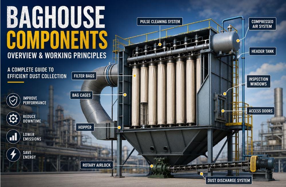
Complete Guide to Pulse Jet Baghouse Components, Failure Mechanisms & Maintenance
Table of Contents
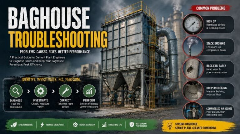
A Pulse Jet air baghouse performs efficiently only when all its components work together as designed. However, when baghouse performance starts to decline, the first response in many cement plants is often to increase pulse cleaning frequency or raise compressed air pressure. While these adjustments may temporarily reduce differential pressure (DP), they rarely address the actual cause of the problem.
In most cases, issues such as a leaking pulse valve, misaligned blow tube, damaged venturi, worn rotary airlock, or poor compressed air quality gradually affect the baghouse long before major symptoms become visible. Ignoring these early signs can lead to higher power consumption, increased emissions, reduced bag life and even production losses.
Effective baghouse troubleshooting begins with understanding the function of every component and how they work together as a single system. In this chapter, we will explore each major baghouse component, its working principle, common failure modes, inspection methods, and maintenance practices to help improve reliability and overall baghouse performance in cement plants.

Related Reading: This article is Part 2 of our Baghouse Optimization series. For the fundamentals of baghouse operation and optimization, read Baghouse Optimization in Cement Plants (Part-1).
1. Filter Bag – The Heart of the Baghouse
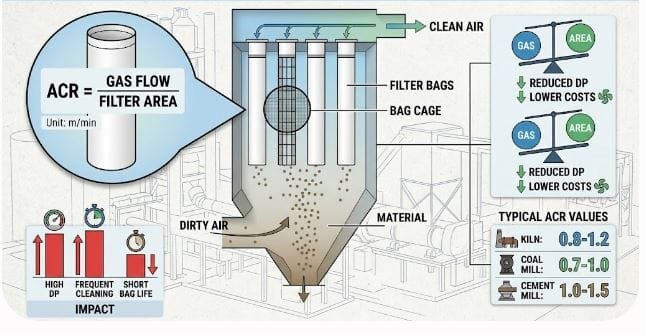
The filter bag is the primary filtration component of a baghouse and is responsible for separating dust particles from the process gas. As dust-laden gas passes through the filter media from the outside to the inside, dust particles are retained on the outer surface while clean air flows through the bag. During operation, a thin layer of dust, known as the dust cake, gradually forms on the filter surface, improving filtration efficiency by capturing finer particles.
Working Principle
During normal operation, dusty gas enters the baghouse and flows around the filter bags. The filter media allows clean gas to pass through while trapping dust particles on its outer surface. As the dust cake builds up, airflow resistance gradually increases. When the differential pressure (DP) reaches the preset limit, the pulse jet cleaning system releases a burst of compressed air that expands the filter bag and dislodges the dust cake. The removed dust falls into the hopper, and the filter bag resumes normal filtration.
Common Filter Materials
The selection of filter media depends on operating temperature, gas composition, moisture content, and dust characteristics. Choosing the appropriate filter material is essential for reliable performance and longer service life.
| Filter Media | Typical Temperature | Typical Application |
|---|---|---|
| Polyester | Up to 150°C | Cement Mill |
| Polypropylene | Up to 90°C | Low-temperature systems |
| Acrylic | Moderate acid resistance | Special applications |
| Nomex (Aramid) | Up to 200°C | Kiln Baghouse |
| PPS (Ryton) | Excellent chemical resistance | Coal Mill |
| Fiberglass | Up to 260°C | High-temperature kiln gases |
| PTFE Membrane | Premium filtration | Low-emission applications |
Related Reading: If you would like to learn more about mill stability, read our article on Common Causes of Vibration in Vertical Roller Mills (VRM) and Their Troubleshooting, where the most common process- and mechanical-related vibration issues are explained with practical troubleshooting tips.
2. Filter Cage
The filter cage is a structural support placed inside the filter bag to maintain its shape during operation. It prevents the bag from collapsing under the negative pressure created by the ID fan and provides the necessary support during pulse cleaning. A properly designed cage ensures uniform airflow, effective cleaning, and longer filter bag life.
Working Principle
The filter bag is installed over the cage, which keeps it fully expanded during the filtration process. When a pulse of compressed air enters the bag, the cage supports the rapid expansion and contraction of the filter bag without allowing it to collapse or deform. This movement helps dislodge the accumulated dust cake from the bag surface, after which the dust falls into the hopper while the bag returns to normal filtration.

In a Vertical Roller Mill (VRM), harder clinker often requires increased fan airflow to transport the additional internal recirculation and maintain efficient material separation. Understanding and accurately measuring actual fan flow is therefore essential for stable mill operation and energy optimization. For a detailed explanation, read Fan Flow Measurement in Cement Plants: Methods, Calculations & Optimization.
3. Venturi
The venturi is an important component of the pulse jet cleaning system that improves the efficiency of filter bag cleaning. It is installed at the top of each filter bag and works by increasing the effectiveness of the compressed air pulse. This allows the baghouse to achieve better cleaning performance without requiring additional compressed air.
Working Principle
During the pulse cleaning cycle, compressed air passes through the venturi at high velocity, creating a low-pressure zone that draws additional clean air into the filter bag. The combined airflow generates a stronger cleaning pulse, causing the filter bag to expand rapidly and dislodge the accumulated dust cake. The released dust then falls into the hopper, while the filter bag returns to normal filtration.
4. Pulse Valve (Diaphragm Valve)
The pulse valve, also known as a diaphragm valve, is one of the most important components of a pulse jet baghouse. Its function is to release a short burst of compressed air into the blow tube to clean the filter bags. Effective pulse cleaning helps maintain proper airflow and stable differential pressure (DP), ensuring efficient baghouse operation.
Working Principle
The pulse cleaning cycle starts when the PLC sends a signal to the solenoid valve. The solenoid releases pilot air, causing the diaphragm valve to open instantly. Compressed air stored in the header tank then flows through the blow tube and venturi, creating a high-pressure pulse inside the filter bag. This pulse expands the bag, dislodges the dust cake from its surface, and allows the dust to fall into the hopper for collection.

5. Solenoid Valve
The solenoid valve is an electrically operated valve that controls the pulse cleaning cycle in a baghouse. Although it is one of the smallest components in the system, it plays a critical role by controlling the flow of pilot air that activates the diaphragm valve. Without a properly functioning solenoid valve, the pulse cleaning system cannot operate effectively.
Working Principle
When the PLC sends an electrical signal, the solenoid valve opens and releases the pilot air. This action causes the diaphragm valve to open instantly, allowing compressed air from the header tank to flow into the blow tube. The compressed air then passes through the venturi, creating a powerful cleaning pulse inside the filter bag that dislodges the accumulated dust cake. Once the pulse is complete, the solenoid valve closes and the cleaning cycle ends.

Recommended Reading: Since clinker quality is closely linked to kiln operation, understanding burning conditions, heat balance, and thermal efficiency is essential for improving cement mill performance. For a detailed explanation of these topics, check out this comprehensive guide on Amazon Kindle.
6. Blow Tube
The blow tube is a distribution pipe that delivers compressed air from the diaphragm valve to each filter bag during the pulse cleaning cycle. It is fitted with nozzles positioned directly above the venturi of every filter bag to ensure uniform air distribution.
Working Principle
When the diaphragm valve opens, compressed air flows into the blow tube and is discharged through the nozzles. The air then passes through the venturi, creating a powerful cleaning pulse inside each filter bag. Proper alignment between the blow tube nozzles and the venturi ensures effective and uniform cleaning of all filter bags.
7. Header Tank
The header tank is a pressure vessel that stores compressed air required for the pulse jet cleaning system. It acts as a reservoir, ensuring that sufficient compressed air is available for every cleaning pulse without causing a sudden pressure drop in the air supply.
Working Principle
Compressed air from the compressor is stored in the header tank at the required operating pressure. During the cleaning cycle, the diaphragm valve releases this stored air into the blow tube, generating a high-pressure pulse that cleans the filter bags. Once the pulse is complete, the header tank is recharged with compressed air for the next cleaning cycle.

Recommended Reading: Since baghouse performance is closely influenced by raw mill gas flow, temperature, moisture, and process stability, understanding Raw Mill operation and optimization can help improve overall baghouse efficiency. For a detailed guide on raw mill operation, troubleshooting, and process optimization, check out this comprehensive book on Amazon Kindle.
8. Compressed Air System
The compressed air system supplies clean, dry, and adequately pressurized air to the pulse jet cleaning system. Since pulse cleaning relies entirely on compressed air, its quality directly affects cleaning efficiency and overall baghouse performance.
Working Principle
Compressed air produced by the compressor passes through filters, dryers, and pressure regulators before entering the header tank. During pulse cleaning, this conditioned air is released through the diaphragm valve, blow tube, and venturi to generate the cleaning pulse inside the filter bags.
9. Rotary Airlock
The rotary airlock is installed beneath the hopper to discharge collected dust while maintaining an airtight seal. It prevents outside air from entering the baghouse and ensures continuous dust removal without disturbing the filtration process.
Working Principle
As dust accumulates in the hopper, it enters the rotating pockets of the airlock rotor. The rotor continuously carries the dust to the outlet while maintaining an air seal between the baghouse and the discharge system. This allows dust to be removed efficiently without introducing false air into the system.
10. Hopper
The hopper is the bottom section of the baghouse where dust released during pulse cleaning is collected before being discharged through the rotary airlock. It is designed to provide temporary dust collection and smooth flow toward the discharge system.
Working Principle
During pulse cleaning, the dust cake detached from the filter bags falls into the hopper under gravity. The hopper directs the collected dust toward the rotary airlock or dust conveying system, where it is continuously removed from the baghouse.

11. Differential Pressure (DP) Transmitter
The Differential Pressure (DP) transmitter is an important instrument that continuously measures the pressure difference between the dirty air chamber and the clean air chamber of the baghouse. It provides the primary signal for monitoring baghouse performance and controlling the pulse cleaning cycle.
Working Principle
The transmitter senses the pressure on both sides of the filter bags and calculates the differential pressure. As dust accumulates on the bags, the pressure difference increases. When the DP reaches the preset value, the PLC initiates the pulse cleaning sequence to remove the dust cake and restore normal airflow.
12. Expansion Joint
Expansion joints are flexible connectors installed between ducts and baghouse equipment to absorb thermal expansion, mechanical movement, and vibration. They help protect the ductwork and connected equipment from stress caused by temperature changes.
Working Principle
As the temperature of the process gas changes, ducts expand and contract. The expansion joint flexes to accommodate this movement while maintaining an airtight seal. This prevents excessive mechanical stress, reduces vibration transmission, and protects the baghouse and ducting system from damage.
13. Access Doors
Access doors are provided on the baghouse to allow inspection, maintenance, and replacement of internal components such as filter bags, cages, and pulse cleaning equipment. They are designed to provide easy access while maintaining an airtight seal during normal operation.
Working Principle
During maintenance, the access door is opened to inspect or service the baghouse. Once maintenance is complete, the door is securely closed using gaskets and locking mechanisms to prevent false air from entering the system and to maintain proper baghouse performance.

14. Inspection Windows
Inspection windows are installed on the baghouse to provide a safe visual view of the hopper, clean air chamber, or other internal sections without opening the access doors. They help operators monitor equipment conditions while the baghouse is in operation.
Working Principle
The transparent inspection window allows operators to observe dust movement, pulse cleaning, or internal conditions without interrupting the filtration process. This enables quick visual inspections while maintaining the airtight integrity of the baghouse.
15. Dust Discharge System
The dust discharge system continuously removes the dust collected in the hopper and transports it to the next stage of the process. Depending on the plant design, it may include a screw conveyor, drag chain conveyor, air slide, bucket elevator, or a combination of these equipment.
Working Principle
After pulse cleaning, the collected dust falls into the hopper and is discharged through the rotary airlock. The dust discharge system then transports the material continuously to storage, recycling, or the next processing stage, preventing dust accumulation inside the hopper and ensuring uninterrupted baghouse operation.
Component Interaction – Why One Small Failure Creates Big Problems
A baghouse is not just a collection of individual components—it is an integrated system where the performance of one component directly affects the others. Even a minor fault, if left unnoticed, can trigger a series of operational problems throughout the baghouse.
For example, a worn rotary airlock may allow false air to enter the hopper. This lowers the process gas temperature and, if it falls below the dew point, moisture can condense on the filter bags. The resulting sticky dust begins to blind the filter media, causing the differential pressure (DP) to rise. To compensate, the pulse cleaning system operates more frequently, increasing compressed air consumption and accelerating filter bag wear. At the same time, restricted airflow forces the ID fan to work harder, increasing power consumption and reducing mill ventilation, which can ultimately affect production.
This example highlights how a seemingly minor mechanical issue can gradually lead to higher emissions, increased maintenance costs, greater energy consumption, and reduced plant efficiency. Understanding these interactions is essential for identifying the root cause of problems rather than simply treating their symptoms.
Key Takeaways
Every component in a baghouse plays a specific role in ensuring efficient dust collection and stable operation. From the filter bag and cage to the pulse cleaning system, compressed air supply, hopper, and dust discharge equipment, the performance of each component directly influences the overall efficiency of the baghouse. A clear understanding of these components and their working principles provides the foundation for effective troubleshooting, preventive maintenance, and long-term baghouse optimization.


One thought on “Baghouse Optimization in Cement Plants (Part 2)”